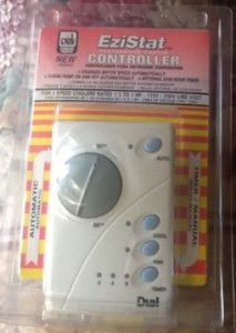
After a swamp cooler switch, a thermostat controller is the next best way to control an evaporative cooler.
These can work the same as a switch only with added features of it being programmable for temperature or run times.
It can still be used as a switch by simply pressing the auto, cool, or fan button.
The use for a swamp cooler thermostat controller is to have a swamp cooler automatically turn off and on depending on the temperature like any air conditioner normally would.
A thermostat controller has the advantage over a switch since a switch needs to be manually turned off and on.
The wiring is a straightforward and easy job but as always, if you do not feel comfortable wiring the controls getting an electrician is always advisable.
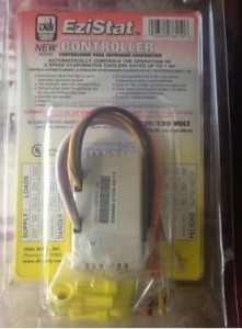
The back of the controller uses wire nuts instead of terminals to screw into.
This is only an example always follow the schematics that come with a controller.
Here is a basic wiring schematic for a thermostat controller

As you can see in the schematic, the Black wire (hot), White wire (common), and Green wire (ground) come from the breaker like any typical appliance.
The other color-coded wiring needs to go to their function, such as the water pump, which goes to the Orange with Black stripe wire, and the thermostat #2 labeled wire.
Other wiring color codes
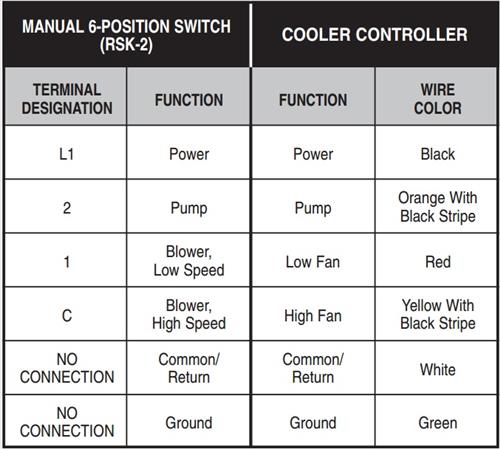
To wire in the thermostat the above would be followed.
For example, L1 is labeled as power which is the black wire from the circuit breaker. All common wires (white) are tied together, so the circuit is completed.
The above is a basic wiring diagram of how to wire up a thermostat for a swamp cooler. This is only an example, and the schematics and wire color coding can change from the thermostat to thermostats, so be sure to check the schematics that come with a controller.
Greg, you must’ve had success in tying into the two white wires capped together “like commons in the box.”
I am writing in hopes of helping the next person.
You can’t cap off the white wire because the cooler won’t operate. The information pamphlet from the Cooler Controller is misleading because it says, “No Connection” and leads one to believe the wire can just be capped. (Although it also states, “If you cannot locate the Return (Common or L2) wire within your existing junction box, then you MUST install a Return (Common, or L2) wire from your cooler to this Cooler Controller junction box.
The wire that you took off the “C” screw is not available because you had to attach the Yellow with Black Striped wire to the wire from the terminal designated “C” for the high speed blower fan. In my instance there were three white wires tied together in the switch (“junction”) box. These are the “Common” wires to which I attached. If you don’t have common wires in the switch box, you’ll have to run from the cooler to this switch box. All five wires must be attached.
The people at Dial Manufacturing are no help. They understand how the unit works, but they’re not savvy enough to help you with your wiring. I spoke with Bryce and he was not helpful.
The cooler controller above does not match the schematic. The cooler controller is missing the green ground wire that is shown in the schematic.
Hi, so based on the above posts, I have a Cooler Control thermostat. There are 5 wires. The remaining wire is the White or Control wire. Where does this go? Or can I cap it off? Thanks for the help.
Did you ever get a response? I am in the same boat I think-replacing old switch style without white common and putting in new electronic one that states it has to connected or it won’t work. I just capped the common on the new one and yes, it did not power up. I see what looks like commons in the box (two white wires capped) so I think I just go into that one but I’m not sure and hate dealing with electrical stuff. If you got a good answer, email me directly since it says on this site it will to post (gdouhan@ucanr.edu).
Greg