If you have an error code on a Daikin mini split, the problem can be found by using a chart with the codes listed.
Sometimes Daikin unit will not be working, and no code displays, in which case the remote control can be used to find the error code.
To use the remote control to find an error code, press the Cancel button on the remote control for 5-6 seconds until 00 is shown on the display.
After the 00 flashes, the Cancel button will cycle through the codes giving short beeps for non-errors and a long beep for the problem error.
Read here for how to find a Daikin error code using the remote control.
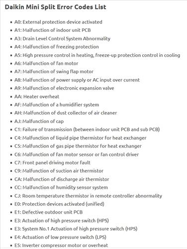
Below are the error codes on the left and the malfunction to the right.
For example, for an E1 error code, it would be a defective outdoor PCB.
The chart also gives possible causes; for example, the E1 could be a defective outdoor PCB or a defective connection of the inside or outside relay wires.
Daikin Mini Split Error Codes List
- A0: External protection device activated
- A1: Malfunction of indoor unit PCB
- A3: Drain Level Control System Abnormality
- A4: Malfunction of freezing protection
- A5: High pressure control in heating, freeze-up protection control in cooling
- A6: Malfunction of fan motor
- A7: Malfunction of swing flap motor
- A8: Malfunction of power supply or AC input over current
- A9: Malfunction of electronic expansion valve
- AA: Heater overheat
- AF: Malfunction of a humidifier system
- AH: Malfunction of dust collector of air cleaner
- AJ: Malfunction of cap
- C1: Failure of transmission (between indoor unit PCB and sub PCB)
- C4: Malfunction of liquid pipe thermistor for heat exchanger
- C5: Malfunction of gas pipe thermistor for heat exchanger
- C6: Malfunction of fan motor sensor or fan control driver
- C7: Front panel driving motor fault
- C9: Malfunction of suction air thermistor
- CA: Malfunction of discharge air thermistor
- CC: Malfunction of humidity sensor system
- CJ: Room temperature thermistor in remote controller abnormality
- E0: Protection devices activated (unified)
- E1: Defective outdoor unit PCB
- E3: Actuation of high pressure switch (HPS)
- E3: System No.1 Actuation of high pressure switch (HPS)
- E4: Actuation of low pressure switch (LPS)
- E5: Inverter compressor motor or overheat
- E6: STD compressor motor overcurrent/lock
- E6: System No.1 Compressor overcurrent
- E7: Malfunction of outdoor unit fan motor system
- E8: Overcurrent of inverter compressor
- E9: Malfunction of electronic expansion valve coil
- EA: Malfunction of four way valve or cool/heat switching
- EC: Malfunction of entering water temperature
- F3: Malfunction of discharge pipe temperature
- F6: Abnormal high pressure or refrigerant overcharged
- H0: Malfunction of sensor system of compressor
- H1: Malfunction of room temperature sensor or humidifier unit damper
- H3: Malfunction of high pressure switch (HPS)
- H4: Malfunction of low pressure switch (LPS)
- H5: Malfunction of compressor motor overload thermistor
- H6: Malfunction of position detection sensor
- H7: Malfunction of outdoor unit fan motor signal
- H8: Malfunction of compressor input (CT) system
- H9: Malfunction of outdoor air thermistor
- HC: Malfunction of (hot) water temperature thermistor
- HF: Alarm in thermal storage unit or storage controller
- HJ: Malfunction of thermal storage tank water level
- J1: Malfunction of pressure sensor
- J2: Malfunction of current sensor of compressor
- J3: Malfunction of discharge pipe thermistor
- J4: Malfunction of low pressure equivalent saturated temperature sensor system
- J5: Malfunction of suction pipe thermistor
- J6: Malfunction of heat exchanger thermistor
- J7: Malfunction of thermistor (Refrigerant circuit)
- J8: Malfunction of thermistor (Refrigerant circuit)
- J9: Malfunction of thermistor (Refrigerant circuit)
- JA: Malfunction of high pressure sensor
- JC: Malfunction of low pressure sensor
- JE: Malfunction of oil pressure sensor or sub-tank thermistor
- JF: Malfunction of oil level sensor or heating heat exchanger thermistor
- L0: Malfunction of inverter system
- L3: El.compo. box temperature rise
- L4: Malfunction of inverter radiation fin temperature rise
- L5: Inverter instantaneous overcurrent (DC output)
- L6: Inverter instantaneous overcurrent (AC output)
- L8: Malfunction of overcurrent inverter compressor
- L9: Malfunction of inverter compressor startup error (Stall prevention)
- LA: Malfunction of power transistor
- LC: Malfunction of transmission between control and inverter PCB
- M1: Malfunction of central remote controller PCB
- M8: Malfunction of transmission between optional controllers for centralized control
- MA: Improper combination of optional controllers for centralized control
- MC: Address duplication, improper setting
- P0: Shortage of refrigerant amount (thermal storage unit)
- P1: Power voltage imbalance or inverter PCB
- P2: Automatic refrigerant charge operation stop
- P3: Malfunction of thermistor in switch box
- P4: Malfunction of radiation fin temperature sensor
- P8: Heat exchanger freezing protection during automatic refrigerant charging
- P9-: Malfunction of fan motor (humidifier unit)
- P9: Automatic refrigerant charge operation completed
- PA: Refrigerant cylinder during automatic refrigerant charging
- PA: Broken wire of heater (humidifier unit)
- PC: Refrigerant cylinder during automatic refrigerant charging
- PE: Automatic refrigerant charge operation nearly completed
- PH: Refrigerant cylinder during automatic refrigerant charging
- PJ: Malfunction of capacity setting (Outdoor unit PCB)
- PJ: Improper combination between inverter and fan driver
- U0: Shortage of refrigerant
- U1 Reverse phase, open phase
- U2: Malfunction of power supply or instantaneous power failure
- U3: Check operation not executed or transmission error
- U4: Malfunction of transmission between indoor and outdoor unit
- U5: Malfunction of transmission between indoor unit and remote controller
- U6: Malfunction of transmission between indoor units
- U7: Malfunction of transmission between outdoor units or outdoor storage unit
- U8: Malfunction of transmission between remote controllers
- U9: Malfunction of transmission (other system)
- UA: Defect of indoor/outdoor power supply
- UA: Improper combination of indoor and outdoor units
- UA: Remote temperature setting wire disconnection
- UC: Malfunction of setting of centralized control equipment address
- UE: Malfunction of transmission between indoor unit and centralized control equipment
- UF: System is not set yet
- UH: Malfunction of system
- UJ: Malfunction of transmission (accessory device)
- 60: External protection device activated (Heat reclaim ventilator)
- 64: Malfunction of indoor air thermistor (Heat reclaim ventilator)
- 65: Malfunction of outdoor air thermistor (Heat reclaim ventilator)
- 6A: Malfunction of damper system (Heat reclaim ventilator)
- 70: System No. 2 Compressor overheat
- 71: System No. 2 Compressor over current
- 8H: Abnormal hot water high temperature
- 90: Abnormal chilled water quantity or abnormal AXP
- 91: System No. 2 Malfunction of electronic expansion valve
- 92: System No. 2 Malfunction of suction pipe thermistor
- 94: Malfunction of transmission (between heat reclaim ventilator and fan unit)
- 95: System No. 1 Malfunction of inverter system
- 96: System No. 2 Malfunction of inverter system
- 97: Malfunction of thermal storage unit
- 98: Malfunction of thermal storage brine pump
- 99: Malfunction of thermal storage brine tank
How to Troubleshoot a Daikin Mini Split
Troubleshooting a Daikin mini split starts with knowing what part of the unit had malfunctioned.
To know which part has malfunctioned, the error code on the unit will need to be looked up on an error code chart.
If there is no code on the unit, the remote control can be used to also pull up errors.
Once the problem is known, more specific causes and fixes can be done to get the system back up and working.
Daikin mini splits are good units that will work for many years with no issues, but sometimes things can go wrong.
When they do go wrong, finding the code and looking it up chart is the first step to solving the problem.
There are many components inside a unit with a code that will display when that component goes bad or fails.
Have you had an issue with a Daikin mini split? Let us know your thoughts below.