Furnaces are generally considered as being the heating part of an air conditioning system. They also serve as the air handling and filtering section of a complete system. Furnaces may be designed to use the various types of gases, fuel oil, or electric resistance elements as the heat source. The type of heat source will also govern the type of heat exchanger construction.
GAS FURNACES
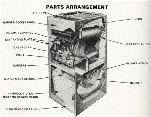
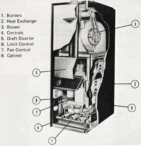
Gas furnaces are manufactured in three designs: upflow, downflow, and horizontal. This terminology refers to the direction of air flow. Each furnace is specifically designed for a particular application. Notice that the burners and flue pipe connection are in a fixed location cannot be changed.
In the downflow furnace, the fan is located on top and the air is blown down through the heat. The duct work, which distributes the air to the separate areas, is connected to the bottom of the furnace.
The horizontal furnace is generally installed in the attic or a crawlspace under the building. The air is blown in a horizontal direction. Generally, these furnaces may be operated with either natural or LP gases. Minor adjustments may be needed along with changing the orifice and in some cases the burner assembly to the proper size.
The manufacturer’s recommendations should regarding these items. Natural gas furnaces require a pressure regulator. LP furnaces do not pressure regulator. LP gas is regulated at the Storage tank.
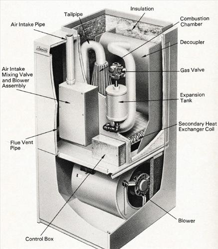
Condesing Gas Furnace.
These types of furnaces, also known as pulse combustion units, have an efficiency from 92 to 99%. This is a improvement over the standing pilot furnaces, which have efficiencies ranging from 55 to 65%.
The unit has a regular valve, but from there several different components are used. These different components are a gas expansion tank with a flapper valve, an air intake mixer valve and blower assembly, a finned cast combustion chamber, a stainless steel “tailpipe,” and a spark plug for initial ignition. Outside air is used in the sealed combustion system, so pulse combustion principle.
This principle ignites small quantities of gas-air mixture at a rate of 60 to 70 times per second.
Each combustion produces from one fouurth to one-half of a Btu. The process begins as air and :is are introduced into the chamber to mix near an ignitor. A spark creates the initial combustion, which in turn causes a positive pressure buildup that closes off the gas and air inlets.
This pressure then relieves itself by forcing the prooducts of combustion down a tailpipe.
As the combustion chamber empties, its pressure becomes negative, drawing in air and gas for the next ignition. At the same instant, part the pressure pulse is reflected back from the end of the tailpipe. It reenters the combustion chamber, causing the gas-air mixture in the chamber to ignite and continue the cycle. Once combustion is started, it feeds upon itself, allowing the combustion blower and spark igniter to be turned off.
OIL FURNACES
These furnaces are designed to use domestic fuel oil as the heat source. They also are available in upflow, horizontal, and counterflow. The horizontal units are designed to be installed on combustible flooring in an attic space, on a slab in a crawlspace, or they can be suspended in a basement, utility room, furnace room, or crawl space. The counterflow oil furnace is designed for installation in either the counterflow or horizontal position.
ELECTRIC FURNACES
Electric furnaces can be in-stalled in the upflow, downflow, and horizontal positions. Note that these furnaces do not have burners or a combustion-type heat exchanger as do the gas- and oil-fired furnaces. Instead electric heating elements are used as the heat source. There are no vent pipe or gas pipe connections—only electrical connections.
It is mainly for this reason that these furnaces are multi positional. All furnaces should be installed with the proper clearances on the rear, sides, and front. These clearances ire specified in the correct installation instructions for the particular furnaces being installed.
HEAT RISE
The heat rise through a furnace can be defined as the temperature increase of the air as it passes through the heating device. That is, the temperature of the supply air minus the return air temperature.
Example: Air is entering the heating unit at 70°F :1.1°C) and leaving at 145°F (63°C). The heat rise is :45°F — 70°F = 75°F (41.7°C). The heat rise through a unit is determined by the amount of heat input to the france and the volume of air flowing through the furnace. Gas and oil furnaces are rated from 40°F (22.4°C) to 100°F (56°C) heat rise. Electric furnaces are generally rated from 40°F (22.4°C) “D 60°F (33.6°C) heat rise.
OIL BURNERS
Fuel oils, like natural and LP gases, are excellent heating fuels. However, the lighting and burning of fuel oil requires special equipment. Fuel oil in its liquid form will not burn; it must be either atomized or vaporized. From this, we can define a fuel oil burner as a mechanical device that prepares oil for combustion. The actual burning of the fuel takes place in the firebox, with the atomizing method being the most popular.
The atomizing type of burner prepares the oil for burning by breaking it up into a fog-like vapor. This is accomplished in three ways: (1) by forcing the oil under pressure through a nozzle (air or steam may be forced through with the oil, or the oil may be alone), (2) by allowing the oil to flow out the end of small tubes that are rapidly rotated on a distributor, or (3) by forcing the oil off the edge of a rapidly rotating cup that may be mounted either vertically or horizontally. Fuel oil burners are divided into three types depending on the operating principle. They are the high pressure, low pressure, and rotary type burners.
HIGH-PRESSURE OIL BURNER
A high-pressure oil Turner is made up of an electric motor, blower, fuel unit, and an ignition transformer. The motor is mounted on the motor shaft and the fuel unit is directly connected to the end of the motor shaft. The fuel unit consists of a strainer, a pump, and a pressure-regulating valve. High-pressure oil burners do not use primary and secondary air as such. They are designed to atomize the fuel oil and mix this atomized oil with the air before ignition.
The fuel oil is forced through the burner nozzle at approximately 100 psig (787.99 kPa). The atomized oil has enough velocity at the nozzle to cause a low-pressure area into which the combustion air is drawn. The combustion air is also under force from the fan, which creates a turbulence in the air.
I have an older natural gas furnace. When the thermostat calls for heat the unit comes on, runs for 30 seconds, shuts off, comes on again, shuts down and then comes back on and runs to temperature.
This is in a home I just purchased so has something been tuned or adjusted to cause this?
It is an older Coleman gas/propane unit in a double wide.